


XATP 2025 Ultra Light Running Poles
October 19, 2025

To ensure the RP004 Ultra Light Running Pole meets the highest standards of safety, durability, and field performance, our team conducted a full product inspection in collaboration with Yang, Sample Testing Engineer from our Quality Inspection Laboratory. The evaluation included 12 standardized mechanical and environmental tests covering all major components.
All testing followed industry-recognized procedures. Results confirm that RP004 meets or exceeds every required performance standard.
1. Handle Puncture Resistance Test
As shown in Figure 1, a static load of 1000 N ± 50 N was applied to the grip within 15 seconds and held for 30 seconds.
Figure 2 shows our product undergoing the puncture test.

.jpg")
Figure 1 Figure 2
Figure 3 indicates the RP004 successfully achieved the full 1000 N load-hold requirement, meeting the standard
.jpg")
Figure 3
2. Handle Tensile Strength Test
Following the setup shown in Figure 1, a static tensile load of 300 N ± 15 N was applied and held for 10 minutes.
Figure 2 shows our handle under tensile loading during the test.

.jpg")
Figure 1 Figure 2
Figure 3 confirms the grip maintained structural integrity throughout the 300 N hold period, fully compliant with the testing criteria.
.jpg")
Figure 3
3. Wrist Strap Tensile Strength Test
A tensile force of 300 N ± 15 N was applied and held for 10 minutes, as illustrated in Figure 1.
Figure 2 shows the wrist strap being tension-tested.

.jpg")
Figure 1 Figure 2
Figure 3 demonstrates the strap successfully sustained the 300 N force, meeting the requirement.
.jpg")
Figure 3
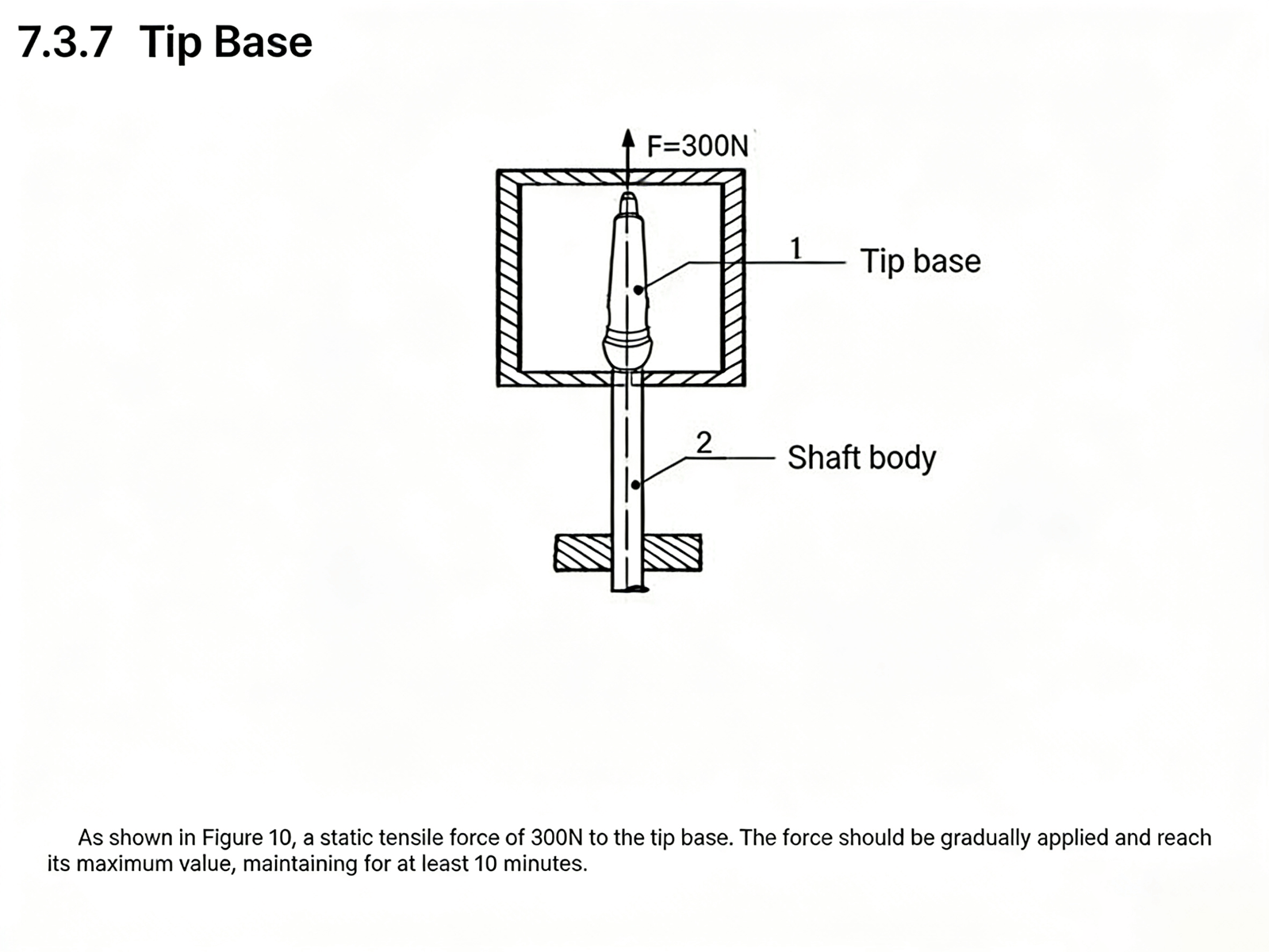
4. Tip Base Tensile Test
Following the method in Figure 1, the tip base was subjected to a 300 N static tensile load for 10 minutes.
Figure 2 shows the tip base under tensile testing.
.jpg")
Figure 1 Figure 2
Figure 3 confirms the RP004 achieved the required 300 N performance standard.
.jpg")
5. Shaft Tensile Strength Test
With the shaft extended to its maximum usable length, a tensile load of 200 N was applied and held for 3 minutes.
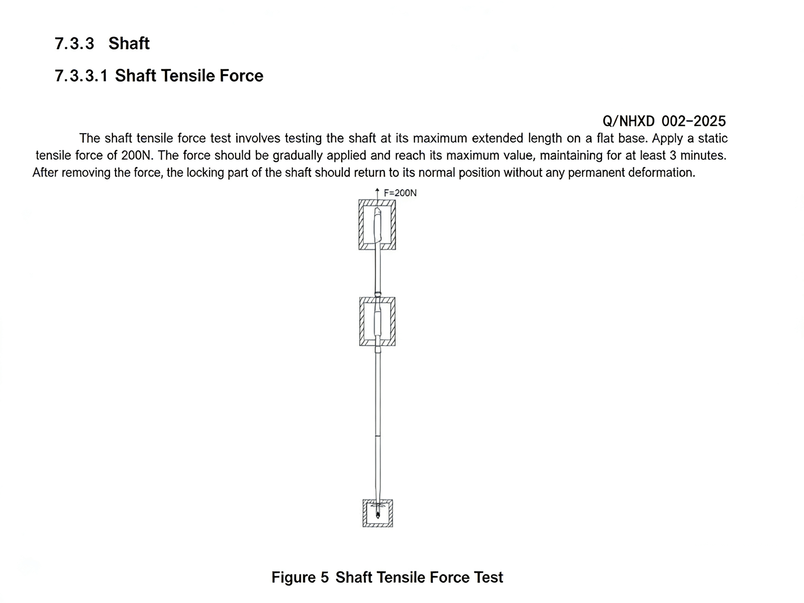
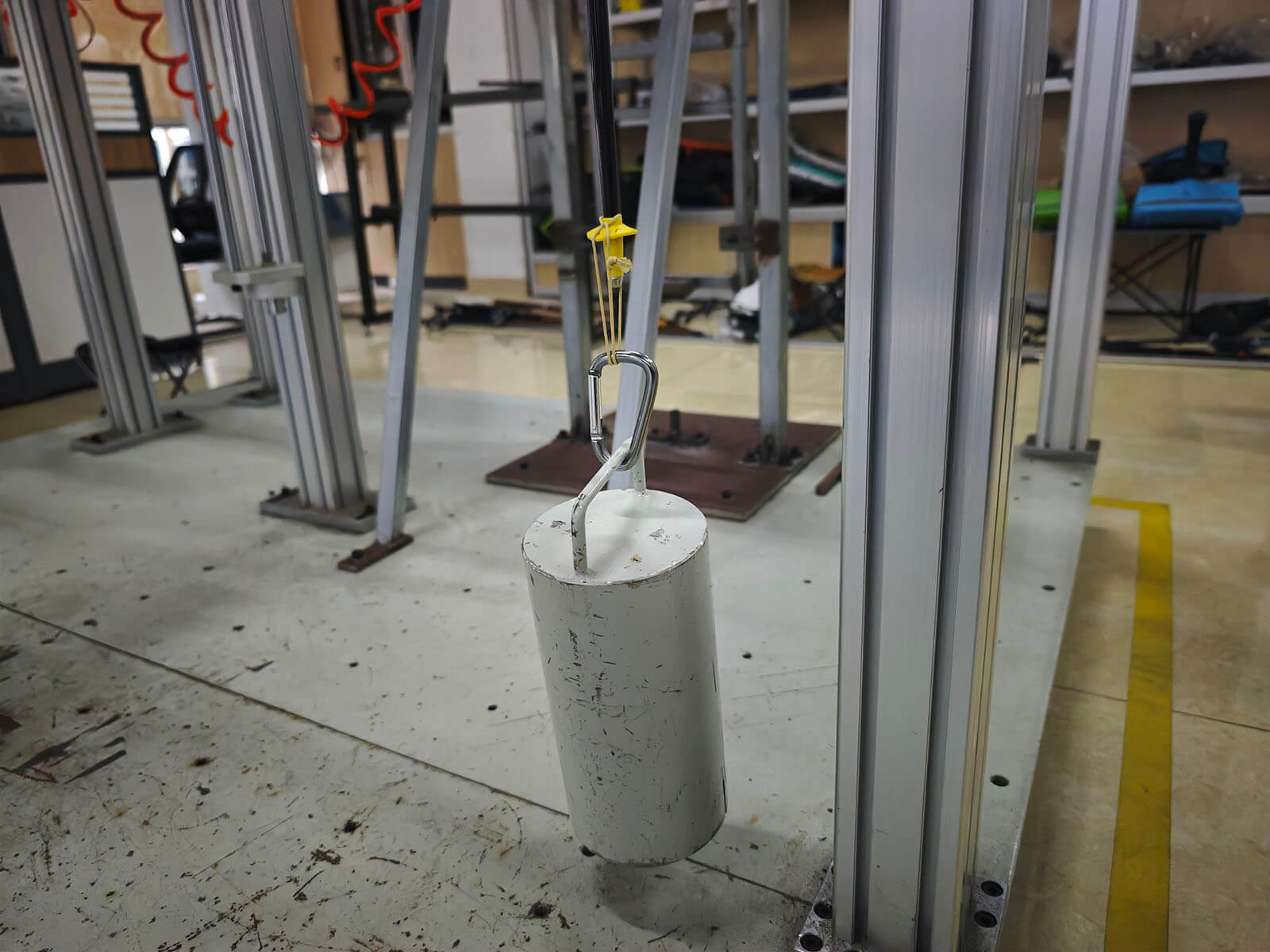
Figure 2 shows our shaft undergoing the tensile test.
.jpg")
The RP004 reached the full 200 N requirement, and the locking system remained stable with no post-test loosening.
6. Locking Mechanism Compression Test
A 200 mm shaft section was locked and loaded with 500 N axial compression for 30 seconds.
Figure 2 shows the locking mechanism under compression.

.jpg")
Figure 1 Figure 2
Figure 3 verifies that the locking system withstood the 500 N pressure without deformation.
.jpg")
Figure 3
7. Locking Mechanism Fatigue Test
Using the same 200 mm shaft section, a repeated 500 N axial load was again applied and held for 30 seconds.
Figure 1 shows our locking mechanism during fatigued load application.
.JPG")
.JPG")
The RP004 maintained full locking performance, passing the fatigue test.
8. Tube Sleeve Tensile Test
A tensile load of 200 N was applied within 15 seconds and held for 30 seconds.
Figure 2 shows the tube sleeve undergoing tensile testing.

.jpg")
Figure 1 Figure 2
Figure 3 confirms the component met the full 200 N standard.
.jpg")
Figure 3
9. Basket Pressure Test
The basket interface was subjected to a 300 N load for 10 minutes.
Figure 2 shows the basket in the pressure-testing process.

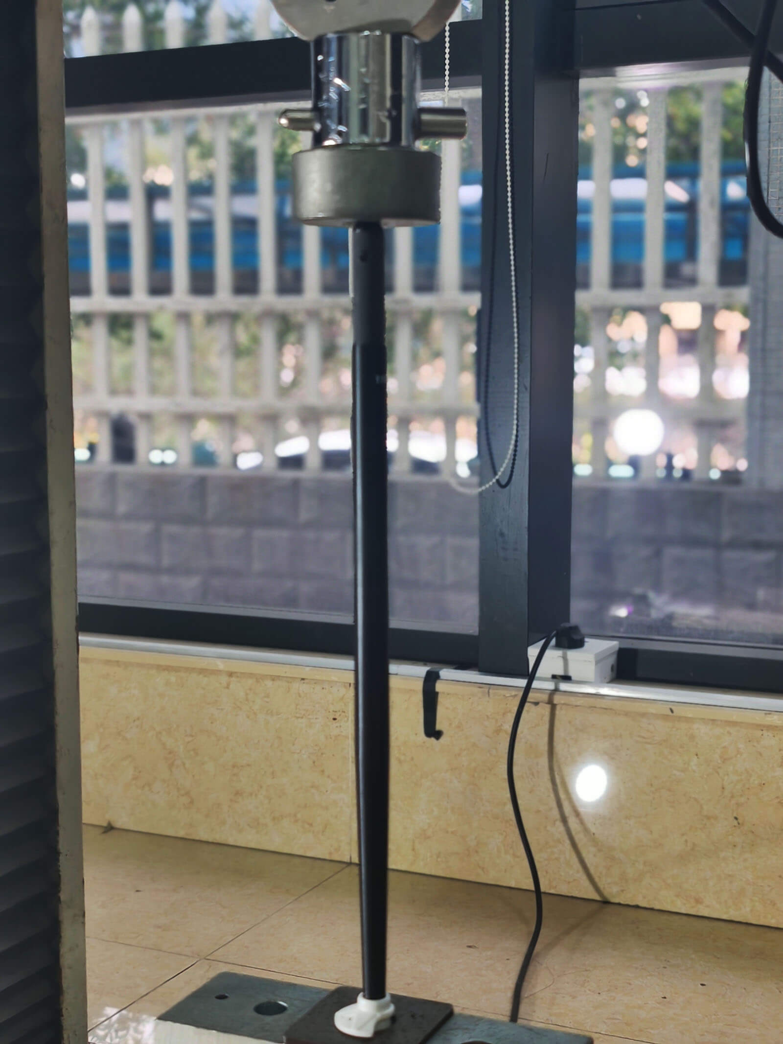
Figure 1 Figure 2
Demonstrates full compliance with the 300 N requirement.
10. Tip Protector Tensile Test
A 40 N axial tensile load was applied within 15 seconds and maintained for 30 seconds.
Figure 1 shows the tip protector during the tensile test.
Figure 2 verifies that the protector achieved the required 40 N load.
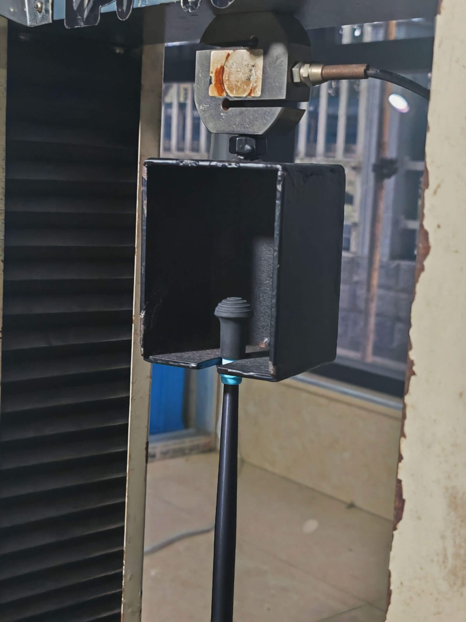

Figure 1 Figure 2
11. Anti-Slip Performance Test at −20°C
With the pole angled at 50° relative to the ground, a 100 N load was applied along the shaft within 15 seconds and held for 30 seconds in a −20°C environment.
Figure 2 shows the anti-slip test being performed under low-temperature conditions.

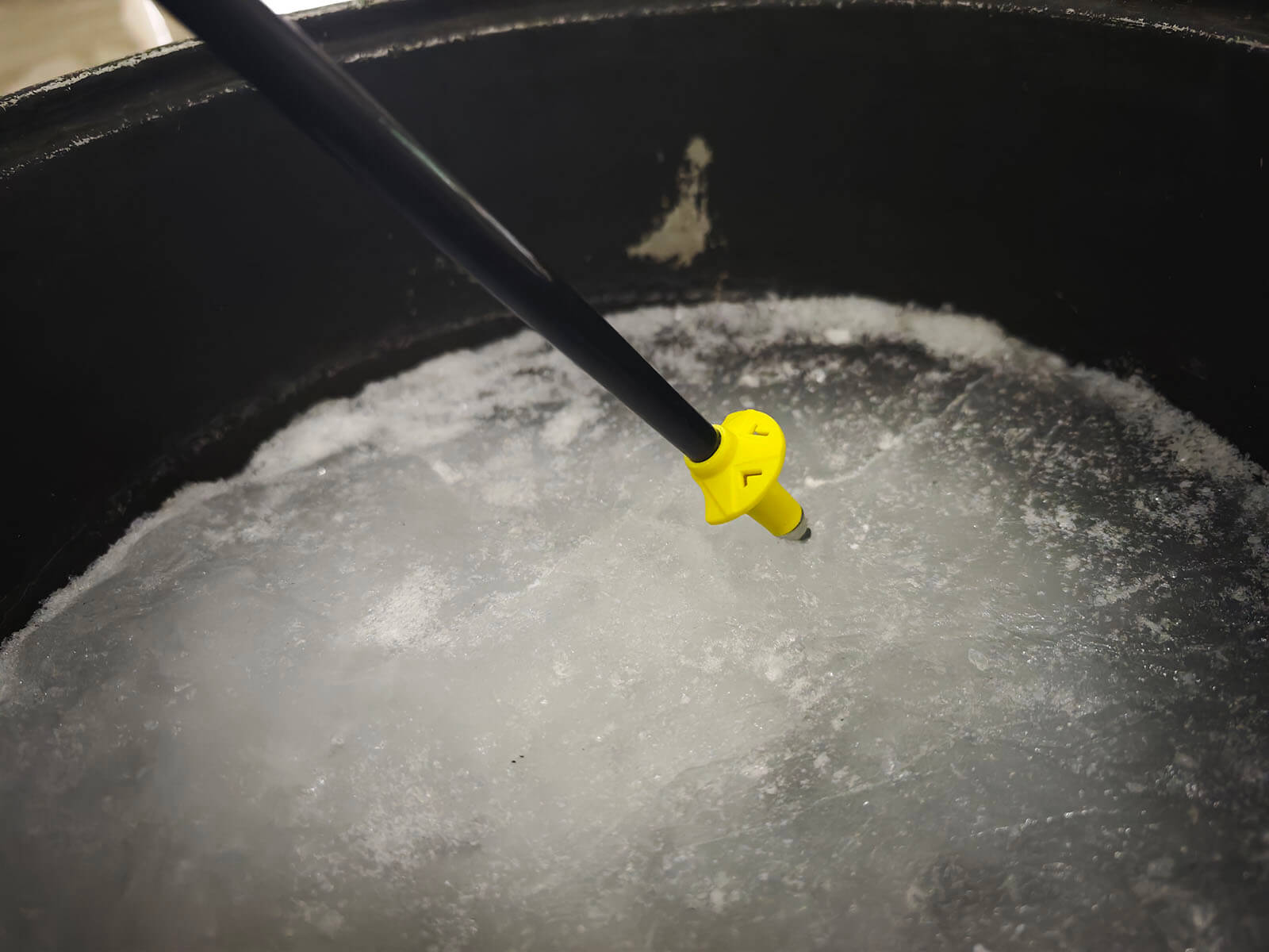
Figure 1 Figure 2
Figure 3 confirms RP004 met the complete 100 N anti-slip requirement.
.jpg")
Figure 3
12. Off-Axis Load Test
At maximum labeled usable length, an off-center axial load of 220 N was applied 10 mm from the shaft centerline and held for 30 seconds.
Figure 2 shows the product under the off-axis loading setup.

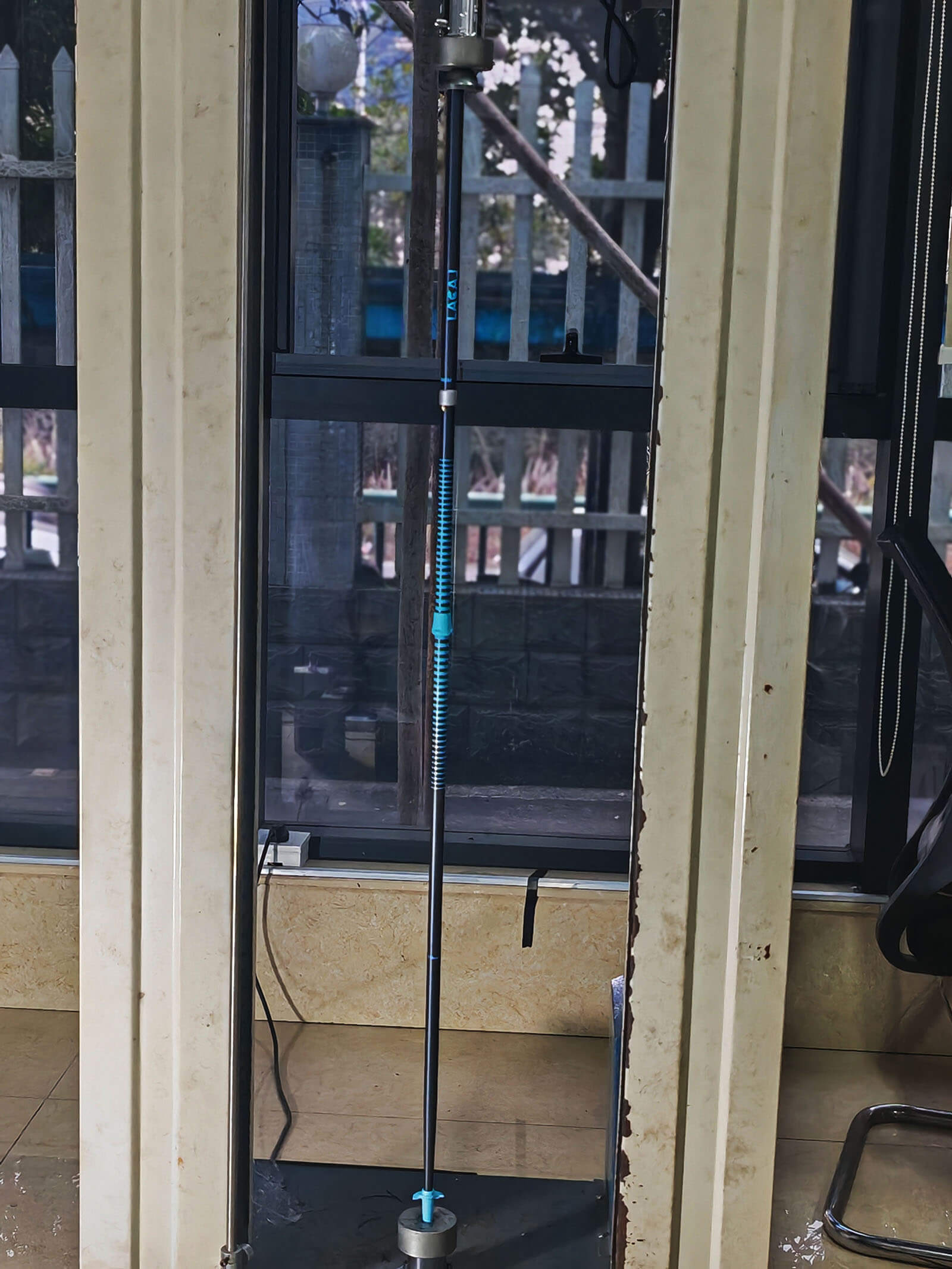
Figure 1 Figure 2
The RP004 withstood the 220 N offset pressure with no bending, fracture, or deformation, and retained smooth extension and retraction after testing.
Conclusion
The RP004 Ultra Light Running Pole successfully passed all 12 major laboratory evaluations, demonstrating robust structural integrity, environmental resistance, and professional-grade performance. These results reinforce RP004’s suitability for competitive running, high-frequency usage, and demanding outdoor conditions.


